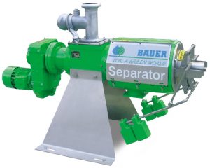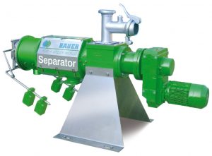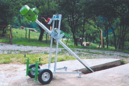
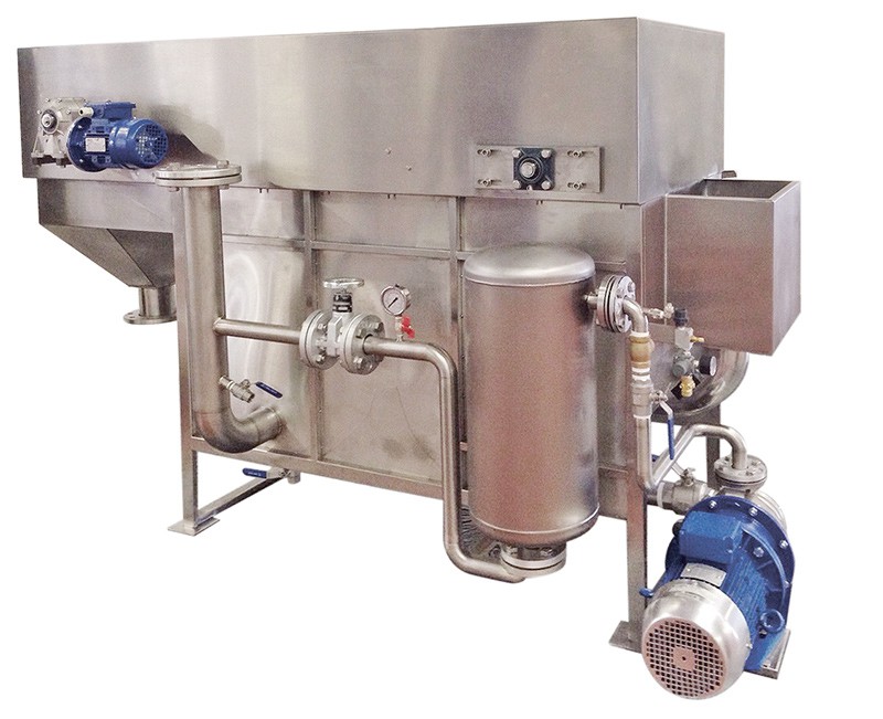
DESCRIPTION AND WORKING PRINCIPLE
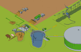
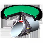
The waters coming from the sites of collection, should be collected in a silo or in a underground tank, which will be used as storage. The chemical-physical flotation plant must be fed at a constant flow rate. In order to protect the flotation unit from solids with size greater than 3 mm, which would cause breakage to the mechanical parts, in particular to the sealing of the saturation electromp, is necessary to put a dynamic or static screen before the flotation unit. The depuration plant with a flotation unit has the aim to remove 80% of fats and SST, in order to reduce the organic load input to the biological purification plant, or to the discharge into the sewer. The plant is completely AUTOMATIC to switch on and off, and for the preparation and dosing of chemicals for coagulation and flocculation of the wastewater to be purified. The reaction of coagulation/flocculation will occur directly in the supply line of the flotation unit, where the coagulant is dosed (PAC, ClFe3) and polyelectrolyte already diluted to the use concentration (0.2-0.3%). The polyelectrolyte will be prepared in a special automatic unit, using the mother product in emulsion or in powder, at request. The flotation unit tank is completely made in stainless steel AISI 304, or, at request, in stainless steel AISI 316. The flotation tank is divided into three compartments, but in a single block.:
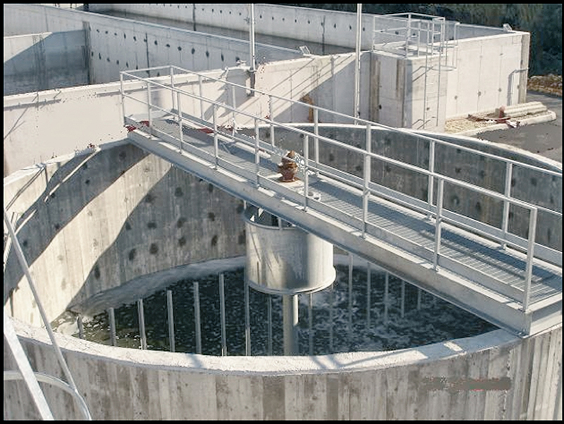
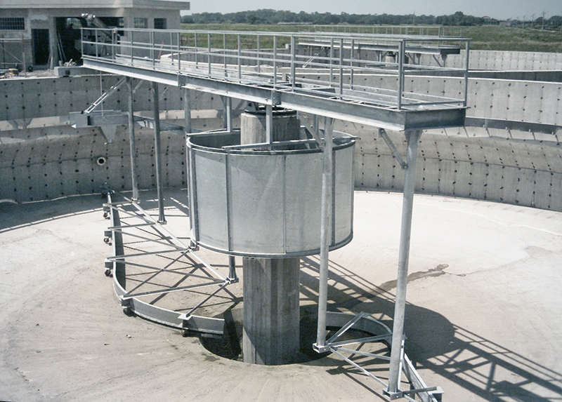
- Saturation tank
- Hopper, with a shape of a truncated pyramid, for the collection of the floated material
- Tank for the accumulation and discharge of the clarified water
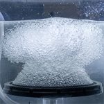
Inside the tank of saturation, due to the air dispersed in tiny bubbles, the coagulated and flocculated wastewater will be dragged quickly on the surface of the liquid where in a few minutes will thicken, and may be evacuated by a series of scrapers dragged by chains and sprockets in stainless steel and transferred to the collection hopper. The saturation of the effluent with compressed air, takes place inside a tank of saturation, of vertical cylindrical shape, suitably dimensioned according to m3/h entering the flotation unit. Inside the tank of saturation, the pressure required is about 3-4 bar, this pressure is regulated by a special diaphragm valve, of type “started flow”. At the first start is established the optimal pressure and this will not have to be changed more. The amount of air inside the tank saturation is dosed by a specific flow meter for air. The amount of air required must be checked at the first start, and must not be changed. The pump saturation, open impeller type, backward with shaft and impeller made of stainless steel, collects inside the tank of saturation a portion of the wastewater of about 3-4 times greater than the amount of wastewater in entry, and sends it to the tank of saturation, where it will occur the contact with the air. Following, is returned at the entrance of the wastewater, air-saturated, so as to allow the pushed upwards of TSS in the wastewater. The clarified liquid will be discharged by gravity, while the thick mud will be transferred by means of progressing cavity pump, into a special tank or thickening tank and then disposed of by self-venting or further dehydrated.
AUTOMATIC OPERATING CYCLE
The whole plant is automatically switched in parallel at the start of the feed pump, and then the electrical panel will receive from the external pump, a signal (clean contact) of the operation of the pump and then of the arrival of the wastewater:
- Saturation electropump
- Compressed air solenoid valve
- Chain gear motor
- Coagulant dosing pump
- Flocculant dosing pump
The switching off of the plant is calibrated, with an adjustable delay in minutes, at the de-energizing of the electrical feeding pump. During operation, the saturation electropump and the electric pumps for the chemicals dosing, will function in a constant way, while the gearmotor of the catenary for the evacuation of the flotated, with timer function “pause-work”, adjustable in minutes, to have the necessary time for the lift of the suspended solids. In case is present the single screw pump for evacuation of the flotated, the pump will run and then turn off, in parallel to the motor of the catenary. The preparation of the diluted polyelectrolyte is automatic and can be made of stainless steel (monobloc tank) or in two tanks in PVC, one for the preparation and one for the storage of the polyelectrolyte.
The water line network is intercepted by a solenoid valve that is controlled by level probes resistive, (three-pointed probe) which indicate when the solenoid valve should be opened (at the minimum level) and when it shall close (to reaching the maximum level). During the passage of water for the filling, in the same current will be injecting the polyelectrolyte, in emulsion or in powder form, dosed from the progressive cavity pump or from the powder doser, timed so as to obtain the concentration of use. The polyelectrolyte prepared will be constantly mixed by a slow agitator, and dosed with a dosing pump piston with stainless steel head, for flow rates up to 500 l/h, or positive displacement pump with the head in stainless steel for higher flow rates.
CONSTRUCTION MATERIALS
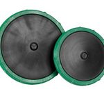
- Flotation tank: Stainless Steel AISI 304/316
- Floated material evacuation and dragging chain: Stainless Steel AISI 304/316
- Guide chain: Polizene 1000
- Plates for the dragging/collection of the flotated material: Stainless Steel AISI 304/316 – Rubber (thickness 10mm)
- Chain shafts and pignon: Stainless Steel AISI 304/316
- Saturation tank discharge valve: Stainless Steel AISI 316
- Saturation valve (started flow type): Spheroidal Cast iron GG25 with NBR membrane
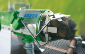
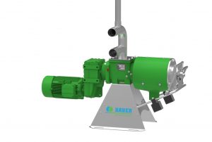
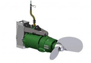
- Saturation electropump: Centrifugal pump with open impeller and backward in Stainless Steel AISI 316
- Air flow meter: Plexiglass
REGULATION
The flotation unit is dimensioned according to the input flow rate, the amount of TSS and the type of waste, for example for the application in cured meats factories and creameies, there is the need of pipes with larger sections, due to the significant amount of fats present in the wastewater. From the model X-FL 300, is allowed both the adjustment of the liquid level inside the tank of saturation, both the height adjustment of the catenary and the scraping blades. This is to optimize the consistency in percentage of dry product floated. The X-FL 100 and X-FL 200 have the only adjustment of the liquid level. The standard models and their characteristics are described in the following table. It is possible to customize the machines to flow rates lower or higher than those described.