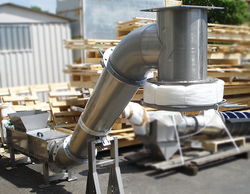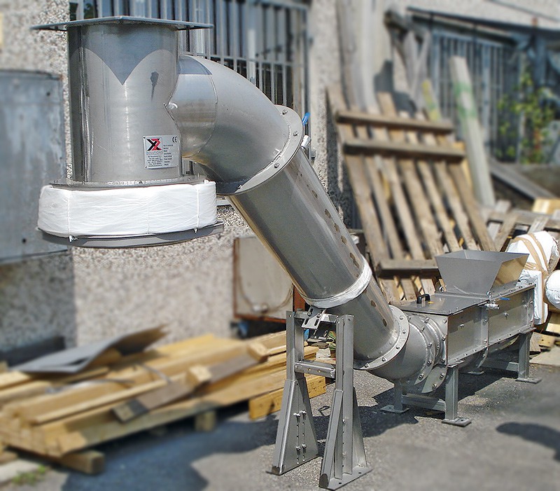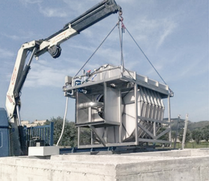
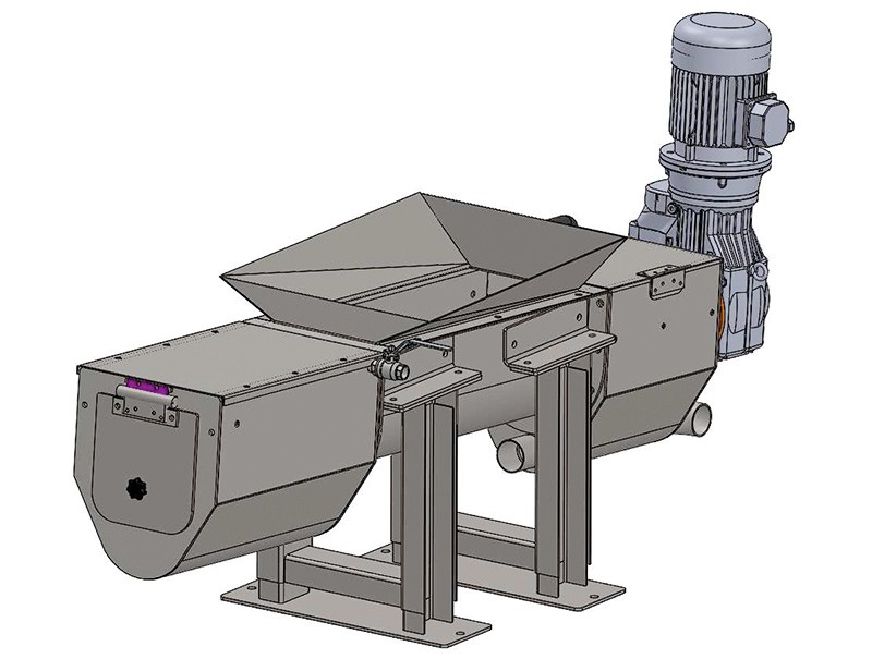
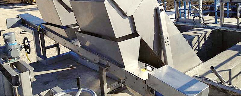
DESCRIPTION AND WORKING PRINCIPLES
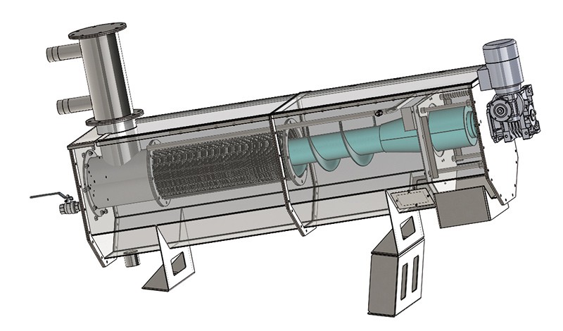
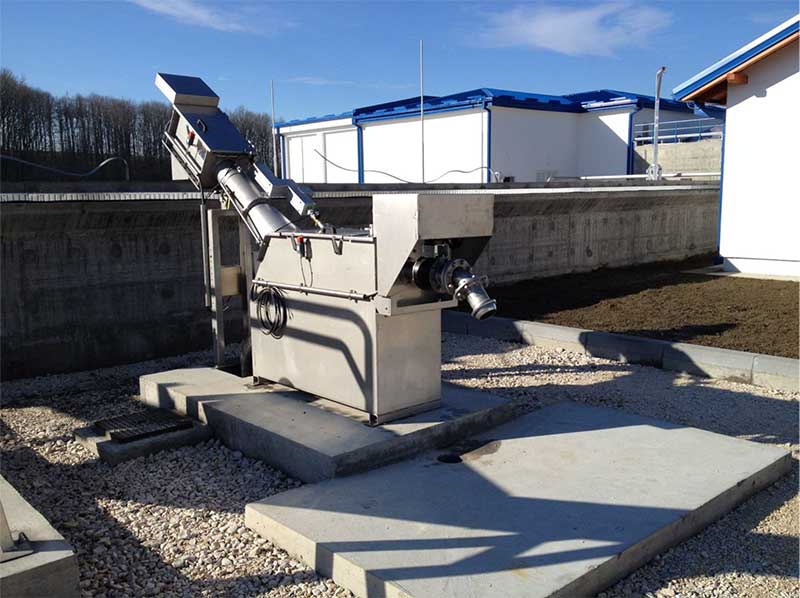
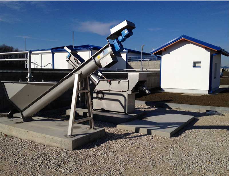
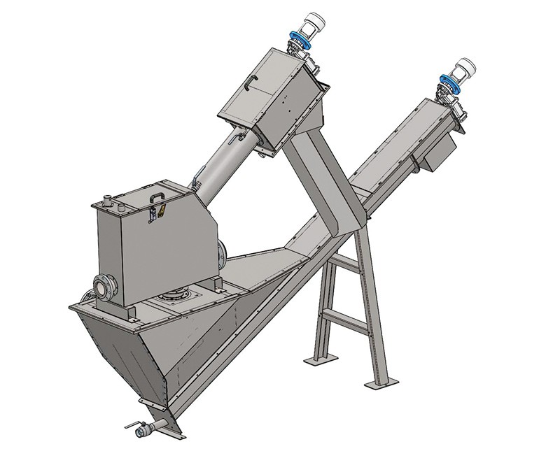
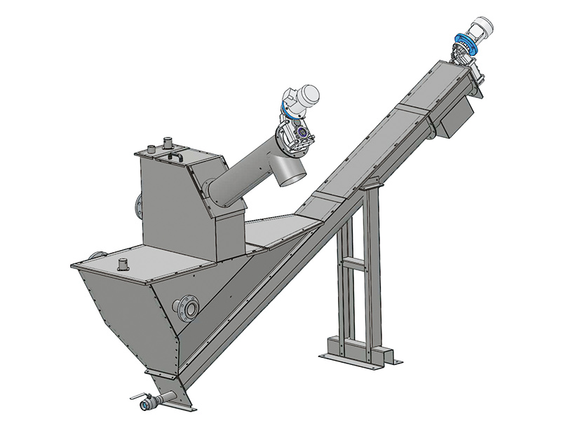
The X-S-COMP Shaftless screw compactor allows to combine three operations: draining, conveyng, compacting. The machine consists of three sections: the draining section, usually placed before the hopper where the majority of the water is discharged; the conveying section, that moves the material to the compacting/dewatering section, where both the volume and the weight reduction take place (up to 50%).
The screw is usually connected directly to the drive system. The working range of the machine is 5° to 35°.
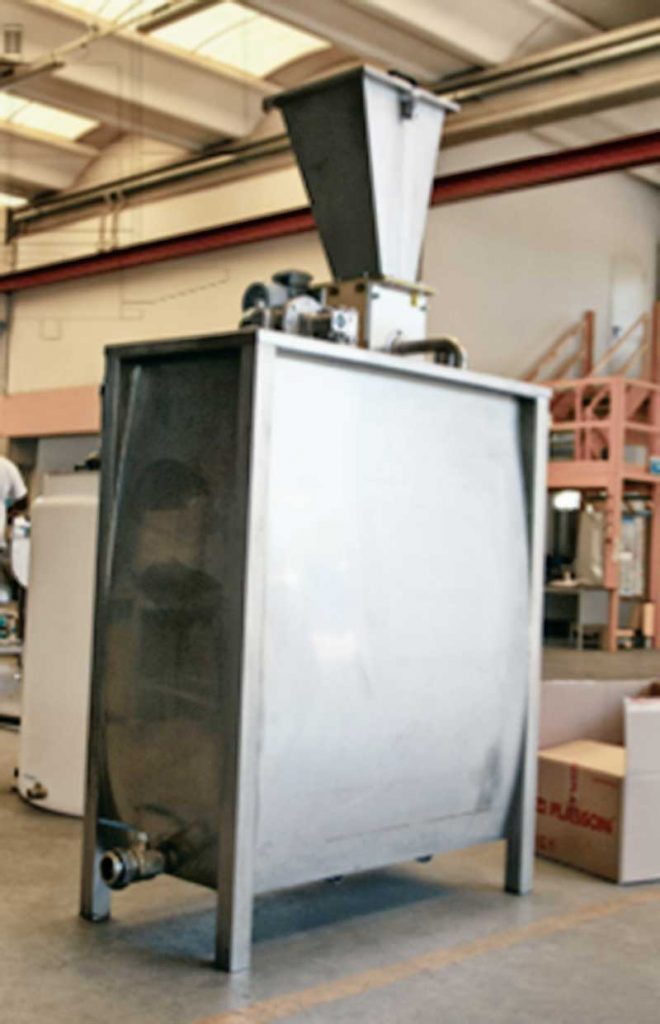
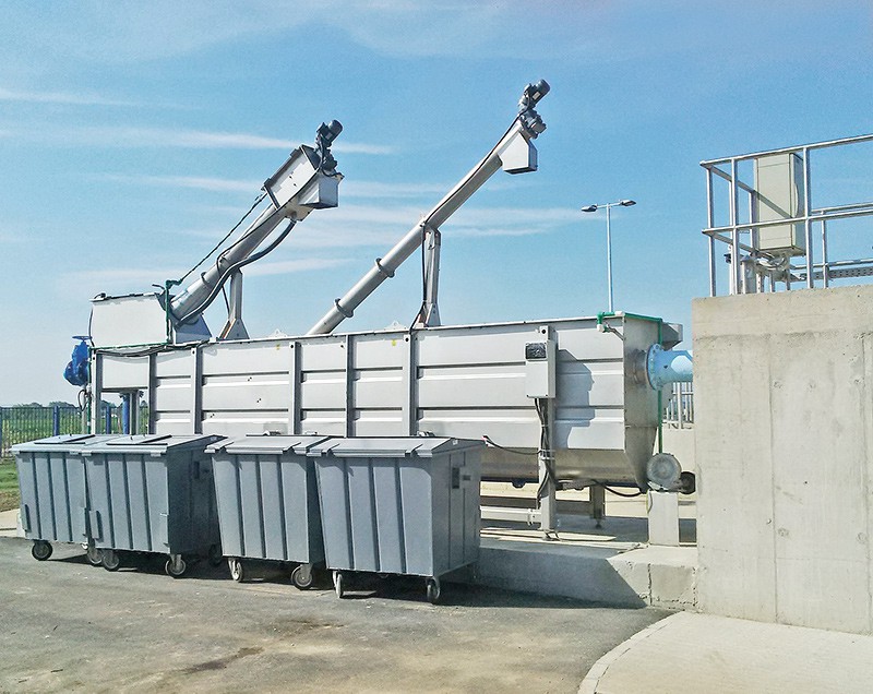
The operation of the machine starts from the entrance of screenings in the hopper. The material is then conveyed up to the area of compaction and dehydration through the shaftless screw conveyor, then is downloaded into a bin. The volume of the screenings can achieve a reduction of up to 40% or more. The water drained from the compaction zone is conveyed at the entrance of the machine, where it can be discharged or possibly reused for other treatments.
MANUFACTURING FEATURES
- Screw: high strength carbon steel or stainless steel AISI 304/316
- Structure: galvanized iron or stainless steel AISI 304 or 316
- Length: the maximum length depends on the overall specifications (power and diameter) and can be up to 20 meters.
- Trough Protection: HDPE liner or bolted stainless steel wearing bars.
- Drive: the maximum power and depends on the inclination, the flow rate and the length
As an option, we can provide a bagging single or continuous system, both with the function of collecting the screeningin order to should not come in contact with the staff of the plant, and also to avoid the escape of odors. The machine can also be supplied of a system of automatic washing commanded by a solenoid valve for the drainage area and compaction.